Pictures of the install of heated seats from heatedseatkits.com
in my 2006 F250.
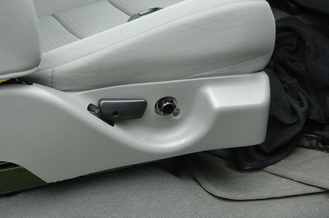
- Picture 1 shows the seat still installed
right after removing the lumbar support knob.
This required a fairly sizeable amount of force. Apparently turning the knob so
there is no tension on the cable might make it come off more easily.
Removing the seat requires removal of 4 18mm bolts/nuts. There are 2 bolts
in the front and 2 nuts in the rear. Disconnect the connector that doesn't
go to anything on the passenger side. (I wonder if this is for non-crew cab
trucks with passenger airbag sensors), remove the seat.
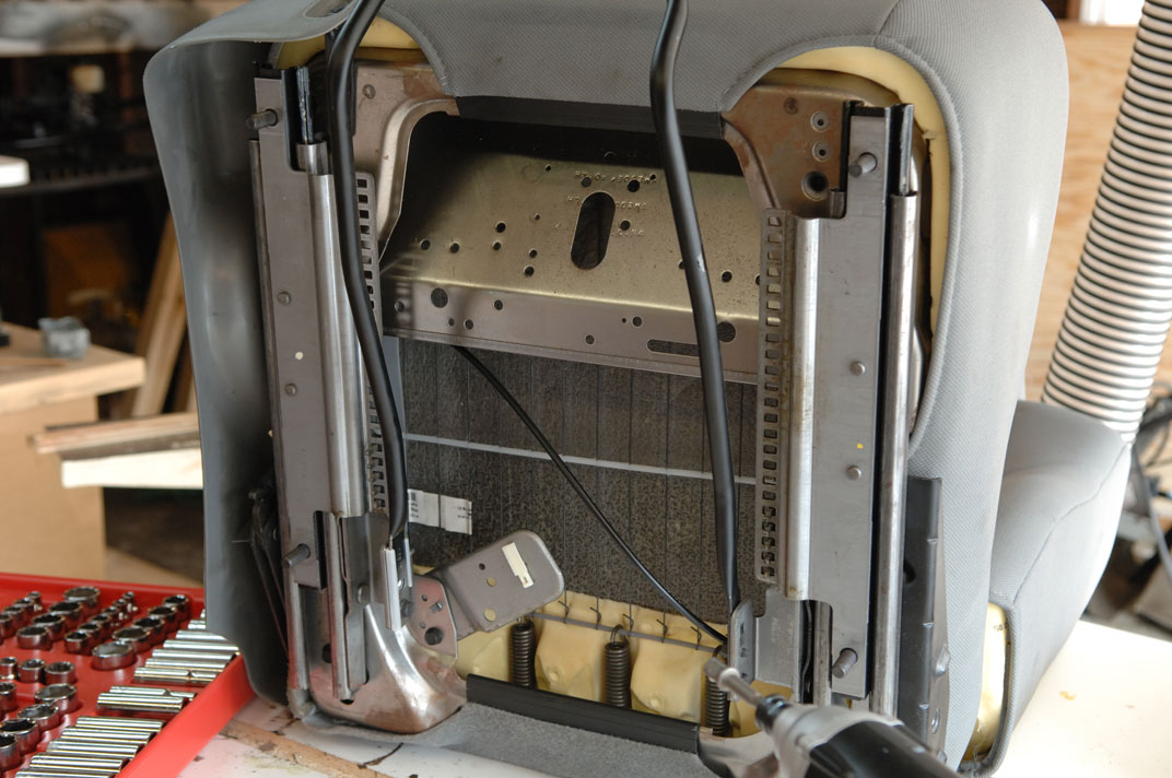
- Remove the black runners that hold the seat in the truck. I believe this
required a 9/16" socket. There are four nuts that connect to the 4 black studs
shown in Picture 2.
- Next, remove the seat position brackets. There are four bolts that hold
them on. I believe they were 13mm bolts. There is one bolt head barely visible
just at the end of the metal track in the bottom left corner of picture 2,
right along a line extending backwards from the metal bracket that held
the unused connector.
- At this point, you can start removing trim pieces. The plastic trim
shown in Picture 1 is held on by the tilt
adjuster lever (which is held on by one phillips screw), 2 more phillips
screws (one behind the tilt lever, one under the lumbar knob as visible in
the picture), and one annoying push plug in the back. The plugs have little
plastic barbs on them that help hold them in. I've found that if you can get
a pair of needle nose pliers under the heads you can work them back and
forth gently and remove them.
- Once the trim is removed, you can start working the fabric covers off.
They are held in place by "J" shaped plastic channels as shown in Picture 3. The front and back edges can be tricky
to remove. Stretching the fabric towards the connectors helps. Warning: The
exposed metal edges under the clips are sharp and easily shred fingers.
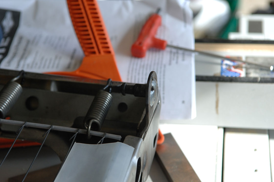
- It is convenient to separate the two halves of the seat. To do this, the
black spring/tilt mechanism needs removed. This is done by removing the two
13mm black bolts. At this point, the seat is held on by a metal stud on the
opposite side. Weding a screw driver between the top and bottom will help you
push the top off the post. The post is shown in Picture 4. This is the same sort of post that
keeps the rear 40% seat connected to the 60% seat on the crewcabs. You'll
also need to remove the seatbelt connector. This requires a T45 torx.
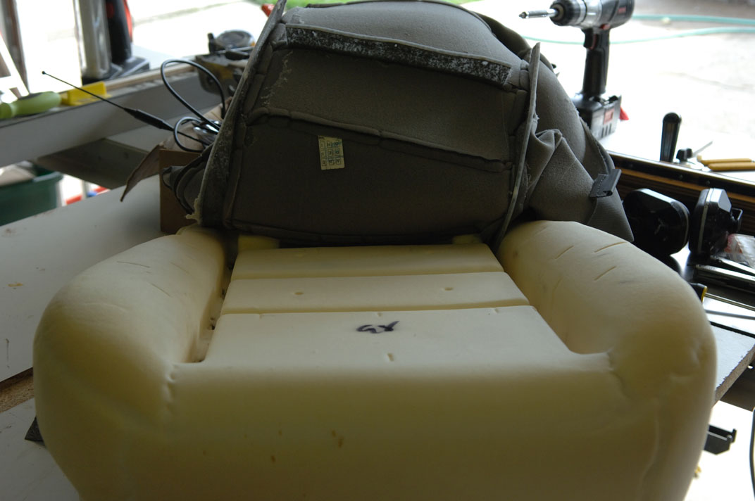
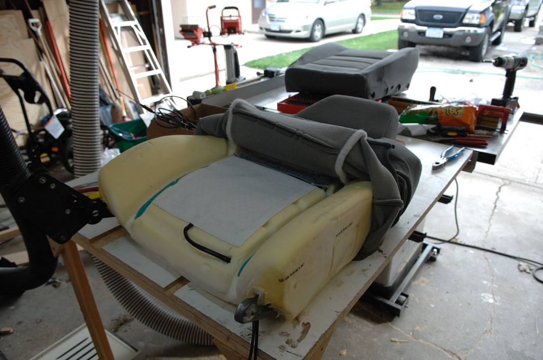
- Picture 5 shows partial removal of the
seat covering. Hog rings are located in both front-to-back channels. The
rings are small metal clibs that go through the upholstery around the plastic
channel and around a metal rod running front-to-back in the foam. I had
plenty of new rings so I cut the existing rings as I worked the cover off.
There are 4 rings per channel, plus 3 rings in the rear two side-to-side
ridges.
- Picture 6 shows a heating element on the
foam. In my opinion the directions are hard to follow for what to do with a
deep side-to-side ridge such as the one in the front of the seat. The install
kits come with some tape and the directions tell you to punch holes in the
heating elements and cover them with tape. I think the holes are mostly
to make it possible to re-attach the plastic anchors to the foam. Notice the
wires ties where hog rings used to be. These will be used so there is no
metal on the heating element. I also cut out some foam for the wire to run
through, plus punched a hole for the connector to exit out the bottom.
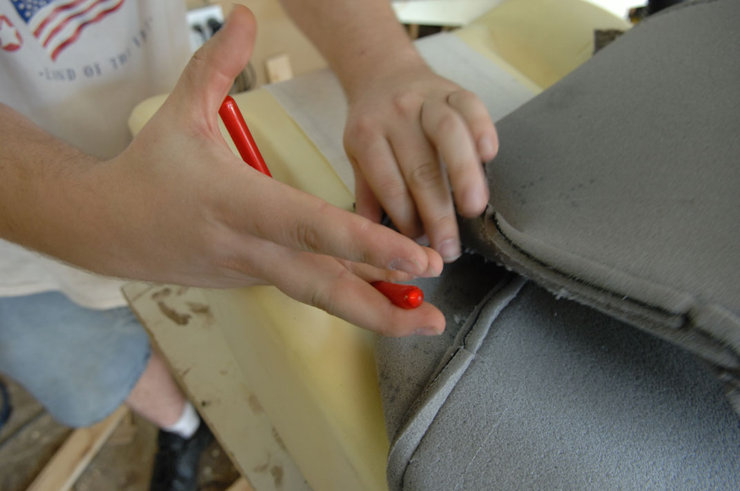
- Picture 7 shows reattaching a hog ring with
the special pliers. The rings are U-shaped staples. The pliers have a groove
in them that helps hold the rings securely while crimping them on. Basically
you stick the ring through the a piece of cloth hanging down from the
upholstery. At the bottom of the cloth is a plastic strip. The ring is meant
to go above that strip. The crimping action closes the pointed parts around
the metal strip running along the channel. I'll take some pictures of this
part when I do the drivers seat. But really it is harder to describe than to
do.
- Picture 8 shows the upper seat getting the
element installed. The upper seat has velcro strips along the top-to-bottom
edges instead of hog rings. There are two sets of hog rings though in the
side-to-side channels -- one at the very top here that I didn't need to cut
and one in the next strip down. Removing the covering on the top is much
easier. There are 2 of the "J" strips that just interlock with each other.
Running a screwdriver blade along the edge separates them easily.
- Picture 9 shows the seats back together
with the wiring visible in the left of the picture. The control box is
wiretied to the metal bracket that holds the connector that doesnt go to
anything on the crewcab seats.
- Picture 10 shows the mounting location for
the seat. The connector that doesn't go to anything is the black and gray
connector in the foreground. The two black boxes are the fuses, one for the
drivers seat and one for the passenger seat. More on my wiring in a bit.
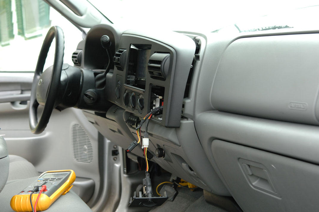
- Picture 11 shows the dash moved out of the
way for wiring the controller switch. I decided I'd prefer dashboard controls
rather than the factory locations (which I believe is near the lumbar adjust
on the side of the seat) just so I can tell when the heaters are on. One
switch is installed next to the power point as seen here. The driver's side
switch is installed next to the power pedals switch location.
My wiring was a bit more complicated than some people might end up doing. I
strung 3 wires from the passenger control switch under the radio and down the
gas pedal side of the front console. The 3 wires from the driver's side
switch also go down this side, along with 2 sets of RCA cables for the AVIC
Z1. Another 2 sets of RCA cables plus wires for the rearview camera go down
the passenger side of the front console. I have 2 layers of dynamat extreme
and a layer of 1/2" foam on the floor so I cut channels for these wires. The
wires run back along the transmission tunnel. A 12 gauge power wire runs from
the back to the passenger side. This connects to the power wires for both
seats. I have some pictures of this wiring I'll post soon.
The 12 gauge wire runs to a bank of relays that are all turned on by a 12V
accessory wire. These relays in turn are connected to a fused distribution
block for the amps, overhead LCD, scanner, invertor, etc. All of this is
powered by a 1/0 ga run from the battery.
The more simple wiring would be to try to find an unused 20A circuit in
the main fuse panel and use it.
So far, I've only done the passenger seat. I'll do the driver's seat
this weekend hopefully. Time from start to end was about 2hrs, 15 minutes
from timestamps on the pictures. I magine I can do the next seat in about
90 minutes. The elements take ~10 minutes to get warm and maybe ~15 to get
nice and toasty. This is a little longer than I'd like but not too bad.
On really cold days I let the truck warm up that long anyway, so it will be
perfect :)
The kits seem pretty reasonable for the price. My only complaint would be the
rather poor German to English translation of some of the manual. Note: The
instructions on the web are only about 1/4 the instructions you get with the
kits. Also, I'd recommend getting the install kit when you order from the
website. It comes with hog rings and hog ring pliers.